A stable and fast network connection depends heavily on proper Ethernet cable termination, and at the heart of this process is the RJ45 connector. Understanding the wiring standards is essential for anyone working with networking cables, whether in home setups, office environments, or industrial installations. One of the most important aspects is the RJ45 connector wiring color sequence explained, which determines how signals travel between devices without errors or data loss.
Incorrect wiring can lead to slow speeds, intermittent connectivity, or complete network failure. That’s why learning the correct color coding standards such as T568A and T568B is crucial. In this guide, we will break down the RJ45 wiring color sequence, explain both standards, and show how proper termination ensures reliable Ethernet connections.
Understanding RJ45 Connector Basics
The RJ45 connector is an 8-pin modular plug used primarily in Ethernet networking. Each of the eight wires inside a standard twisted pair cable has a specific role in transmitting and receiving data signals. These wires must be arranged in a precise order before being inserted into the connector.
Without following the correct wiring pattern, the electrical signals can become misaligned, resulting in poor communication between devices. This is why the RJ45 connector wiring color sequence explained is a fundamental topic for network technicians and IT professionals.
T568A Wiring Standard Explained
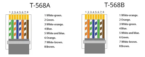
The T568A standard is one of the two widely accepted wiring configurations for Ethernet cables. It defines a specific order for the eight wires based on color coding to ensure consistency across installations. In this arrangement, the green pair is placed first, followed by the orange pair, and other color pairs in a defined structure.
When using T568A, the typical color sequence is: white/green, green, white/orange, blue, white/blue, orange, white/brown, and brown. This arrangement is often recommended for residential installations and government projects due to its backward compatibility with older telephone systems.
The RJ45 connector wiring color sequence explained through T568A ensures proper signal distribution and reduces the risk of cross-talk between wires. By maintaining standardized wiring, network stability is significantly improved.
T568B Wiring Standard Explained
The T568B standard is the most commonly used wiring scheme in commercial and business environments. While similar to T568A, it swaps the green and orange pairs, which can affect compatibility if not used consistently across a network.
In T568B, the correct color order is: white/orange, orange, white/green, blue, white/blue, green, white/brown, and brown. This configuration is widely adopted in structured cabling systems and is considered the default in many networking setups.
Understanding the RJ45 connector wiring color sequence explained for T568B is important because most modern Ethernet installations rely on this standard. Using the same standard on both ends of a cable ensures straight-through connectivity, which is essential for connecting different types of devices like computers and switches.
Straight-Through vs Crossover Cable Wiring
Ethernet cables can be classified into straight-through and crossover types based on how the RJ45 wiring is arranged on each end. A straight-through cable uses the same wiring standard (T568A or T568B) on both ends, making it ideal for connecting different devices.
On the other hand, a crossover cable uses T568A on one end and T568B on the other. This design allows similar devices, such as two computers or two switches, to communicate directly without a router or switch in between.
The RJ45 connector wiring color sequence explained becomes especially important here because incorrect pairing can lead to communication failure. While modern devices often support auto MDI-X (automatic crossover detection), understanding these differences is still essential for troubleshooting.
Common Mistakes and Best Practices
One of the most common mistakes in RJ45 wiring is mixing up the color sequence during termination. Even a single misplaced wire can disrupt data transmission and cause network instability. Another frequent issue is untwisting too much of the wire pairs, which increases interference.
To avoid these problems, always follow the chosen standard strictly and double-check the sequence before crimping the connector. Using a cable tester after installation is also highly recommended to ensure proper continuity and signal flow.
The RJ45 connector wiring color sequence explained in practical terms highlights the importance of precision and consistency. Following best practices not only improves performance but also extends the lifespan of your network infrastructure.
Conclusion
Understanding RJ45 wiring is essential for building reliable and efficient Ethernet networks. Whether you choose T568A or T568B, consistency is the key to ensuring smooth communication between devices. The RJ45 connector wiring color sequence explained throughout this guide shows how proper alignment of wires directly impacts network performance, stability, and speed.
By applying the correct standards and avoiding common mistakes, anyone can create professional-quality Ethernet connections that support modern networking demands.